
Parts source
This is a motorized, remote controlled model. The electronic parts are from the Power Functions family of parts, introduced by Lego in 2007. The parts used in this model were lifted from the 2010 set 8043 Motorized Excavator. The set contains motors and controllers allowing for the remote control of four motors.
 |
It contains four medium motors (one shown to the left in the above picture), two remote receivers (one shown in the top middle), two remote controls (lower middle), and one battery box (right). With these components, it is easy to make remotely controlled models, and I would recommend the 8043 set for getting started with Power Functions.
The bucket was also taken from the 8043 set, as were the four linear actuators used to lift the boom and tilt the bucket.
For the wheels, I used the ones from the 8064 Hauler set. These look quite realistic, and are good a good match for construction equipment models.
The model also uses some parts not from these two sets.
Why a skid steer loader?
I wanted to build a compact model with some playability. A skid steer loader is designed to be small and agile, capable of navigating tight spaces. The loaders are often known by the brand name Bobcat, who first popularized the machines.

These days, though, many companies make similar loaders.
With two motors used for the propulsion, two more motors were remaining for use on the scoop mechanism, to power the lifting of the boom and the tilting of the bucket. So the model is a good match for the parts I had available.
The wheels I used are quite narrow, making it possible to design the whole vehicle to be flush with the bucket, as can be seen by the picture below:

This feature is important for the realism of the model.
Steering
Basically, there are three types of steering for road vehicles:
1. Normal steering, where the front wheels rotate about axes close to the ends of either sides of the axles. The turning of the wheels is usually operated with a rack and pinion system.
2. Articulated body. The centre of the vehicle body, between the axles, is articulated. This type of steering is commonly used with wheel loaders and dump trucks.
3. Skid steering. Used on all tracked vehicles, and some wheeled vehicles. The vehicle is steered by letting the wheels on one side move at a different speed, or even a different direction, than the wheels on the other side. This way, the entire vehicle can rotate by letting the wheels move in the opposite direction.
The three methods are illustrated with this video:
By using one motor for the propulsion, and the second for the steering, the two first options are easy to build. However, with both of them, there is a fundamental problem: There is no easy way to centre the steering completely, hence, driving in a straight line is difficult.
By going for the third option, the skid steering, each motor is connected to each side of the drive train. Hence, going straight forward is as easy as driving both motors in the same direction. Skid steer is generally more fun to use as a motorized model.
Transmission
Originally, I intended to use the white clutch 24t cog gears in the transmission, to protect the motors. However, I found that they were slipping too easily, stalling the vehicle. So no clutch gears were used for protection.
This video illustrates how the transmission works:
The yellow 4t knobby gears are used because they can handle a lot of torque. From a mechanical point of view, 12t or 20t bevel gears could also have been used, however, they are not strong enough to handle the torque when driving, and especially when steering the model.
In the picture below, 12t double bevel gears (black), 20t bevel gears (tan), and 4t knobby gears are used for a 90° connection:

The yellow 4t gears are best for low speed/high torque applications, as they don't slip or break easily. However, they can be a bit noisy at high speed. So for high speed/low torque, it is usually better to use the bevel gears.
Bucket mechanism
Two design choices made the construction of the bucket mechanism more complicated, but also better:
The first constraint relates to how to power the linear actuators. The linear actuators are connected to the body of the vehicle with axles. I wanted to design it so that these axles which bear the weight of the boom, are not rotating. This means that I needed to use the special 20t bevel gear with a smooth centre, and one more bevel gear in the drive train. However, this construction is more structurally sound.
This picture illustrates the two ways to power a linear actuator, plus the third, using a universal joint:

1. Here, the grey axle rotates to power the linear actuator. The grey axle also holds the actuator, which I don't like. This would surely be no real problem for the model, it's just that I think an axle should not transfer power and be load bearing at the same time.
2. The black axle which holds the linear actuator does not rotate. The design utilizes the 20t grey bevel gear with a smooth centre. Another 12t gear is used, compared with the first version. Using the grey 20t gear allows for the most articulation of the linear actuator.
3. This is the simplest solution: replacing the bevel gears with an universal joint. However, the joint cannot articulate to the angles needed by my model, so I could not use this version.
The second constraint I put upon the design is related to how the bucket is lifted. When operating the lower actuators to lift the boom, I wanted the bucket to remain at the same angle. This required the system with the grey upper linkage connecting the bucket, which had to be designed very carefully to achieve this goal.

This Toyota skid steer loader has a similar linkage, however, many other models don't:

Weight distribution
By far the heaviest component is the battery box. To avoid the vehicle tipping over, it had to be placed close to the rear axle, leaving little space for the boom and bucket power mechanism. The two motors driving operating the bucket are placed in the centre column, between the battery box and the driver's compartment.
Instructions
Here are some basic instructions which help explain how the model is built
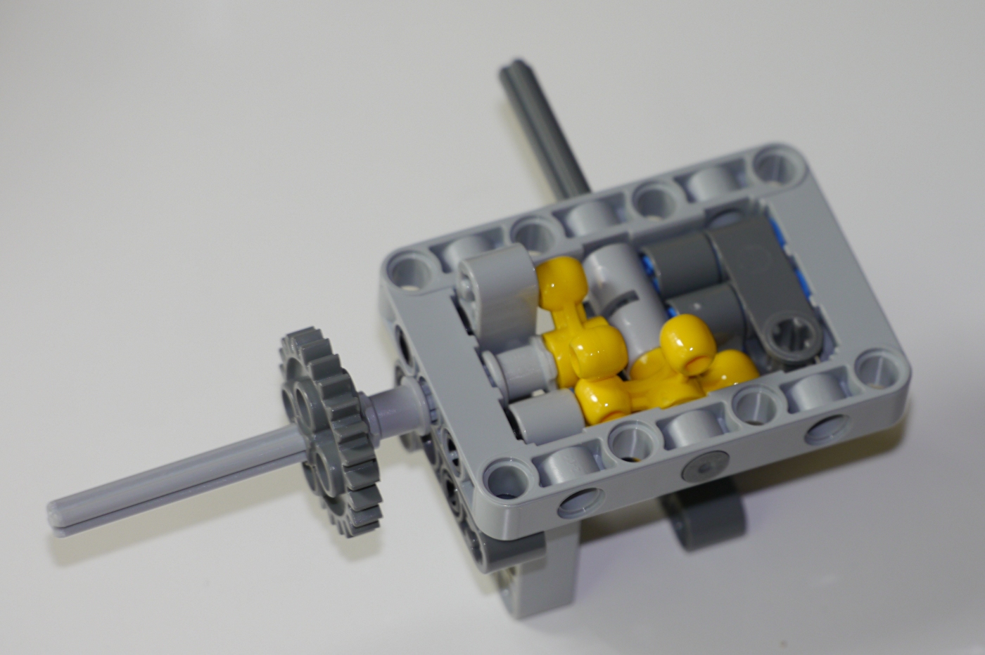
The rear, left side transmission. The motor will be connected to the blue pins:

The same part, seen from below. The yellow 4t knob gears are used for their capability to carry high torque:
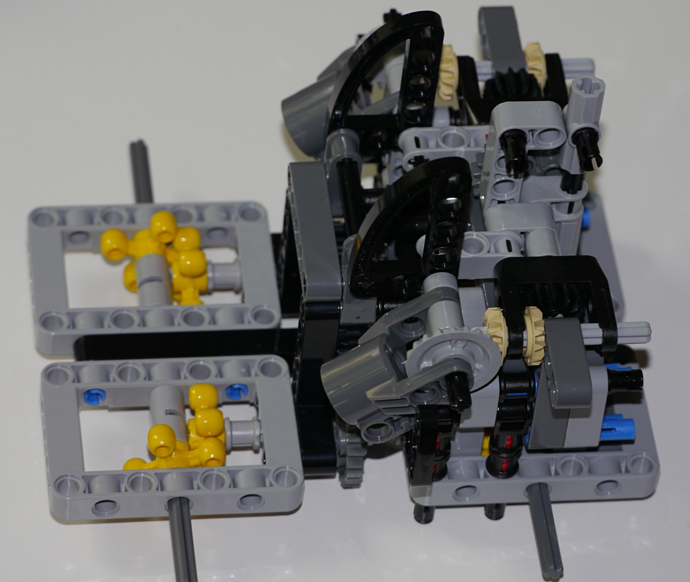
The same rear, left side transmission, but with some additional components:

And seen from below:

Here, the front parts of the transmission have been added, and the right side of the vehicle has been connected. The black 15L beam connects the left and right parts, with the two parts being symmetrical along the black beam:

The linear actuator connectors have been added, and also the grey 20t bevel gears with smooth centre:

And seen from the rear. The two motors for propulsion will be connected to the blue pins:

The motor driving the boom will be connected to the two black pins:
The yellow 15L booms have been added. The white 24t slip gear is connected to the motor with a 3L axle:

Seen from the rear:

The upper motor drives the tan 20t bevel gear with a 5L axle:

These parts are used for connecting the bucket to the boom:

The grey beams are the linkages that tip the bucket:

The bucket is connected with a 10L axle:

The remote receiver controlling the boom/bucket goes in the front:

Some decorative fairing plates are added later:

do you have more detailed photos? i am trying to recreate your model
ReplyDeleteNo, I have uploaded all the photos I took. I don't have any more pictures.
DeleteThis is really terrific. I was looking for ways to build something like this myself for my little boy as he is interested in earth moving equipment at the moment :)
ReplyDeleteTechnic will last forever
ReplyDelete